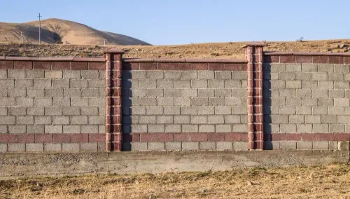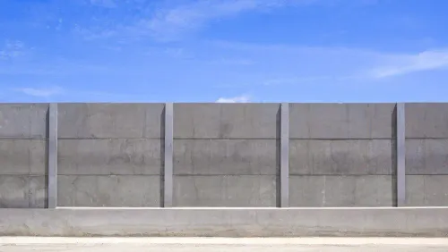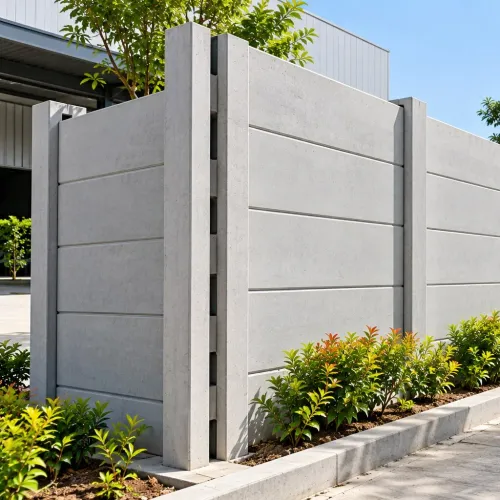
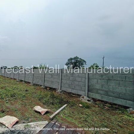
A precast RCC wall can fail before the first panel is lifted if the boundary, soil, footing, post spacing, or access route has not been verified. By the end, contractors will have a site-readiness checklist, a controlled installation sequence, separate checks for 7 ft and 9 ft walls, and a handover record that identifies defects before backfilling.
Key takeaways
- Confirm boundary, setbacks, drainage reserves, utilities, and permissions before excavation.
- Build post pits and foundations to the approved layout and structural drawing.
- Control post spacing, panel alignment, and joint fit during 7 ft installation.
- Add stability checks for taller 9 ft walls before completing handover.
Confirm the Site Before Ordering or Excavating
Do not release fabrication drawings or excavate post pits until the boundary is confirmed on site. Obtain the approved layout, local development permission, road-widening or highway setback records, drainage-reserve limits, and utility-clearance information from the relevant Nashik authority. A structurally adequate wall can still require relocation.
For RCC precast compound wall installation requirements in Nashik, record the following during inspection:
- Mark the legal boundary, gates, existing walls, slopes, nearby excavations, runoff routes, monsoon ponding, and groundwater.
- Detect buried electric cables, water lines, sewers, gas lines, and communication ducts before digging.
- Confirm truck entry, unloading space, crane or lifting-equipment position, safe working room along the boundary, and level storage bearers.
- Identify rock, filled ground, soft layers, black-cotton-type expansive soil, and seasonal drainage. Nashik’s location does not determine footing size; use trial pits or geotechnical information.
- Reject a standard fence panel where a higher plot can press soil against it. Provide separate retaining, drainage, and earth-pressure design.
Use these level references in the drawing:
| Reference | Meaning | Why it matters |
|---|---|---|
| Finished ground level | Final soil, paving, or plinth level beside the wall | Sets exposed height and backfill line |
| Wall-top level | Highest finished point of the wall | Confirms the actual overall height |
| Panel height | Panel dimension above its seat or plinth | Must not be mistaken for total wall height |
Record access constraints before ordering; a crane that cannot stabilise or a truck that cannot turn will delay installation.
Set Out the Boundary and Build the Foundation to the Approved Drawing
Do not size post pits from a nominal 7 ft or 9 ft wall height. Obtain the supplier’s approved system drawing showing post section, post-centre spacing, panel dimensions, reinforcement, concrete grade, embedment depth, footing width and depth, lifting points, and joint details.
- Establish a permanent benchmark and mark finished ground level and wall-top level. Set out corners, gate openings, level changes, and post centres from the approved layout.
- Check both diagonals of each rectangular enclosure, then measure cumulative bay lengths. Recheck the final bay, corner offsets, and gate clearances before excavating.
- Excavate post pits or strip foundations to the drawing. Inspect the base for loose fill, soft layers, water, rock, voids, and nearby excavations before placing reinforcement or concrete.
- Use lean concrete only where the drawing specifies a blinding layer; it is not a substitute for a compacted gravel base or structural footing. Compact gravel in layers where designed.
- Place reinforcement with continuity into the footing, position posts to line, level, and plumb, and brace them until concrete or grout reaches the specified strength. Install panels only after spacing and post stability are rechecked.
The footing must resist vertical load, overturning, and sliding while providing the specified post embedment, drainage, and reinforcement continuity. Corner, end, gate, and abrupt level-change posts need separate details. Loose fill, black-cotton-type soil, slopes, rock, or filled ground require a redesigned foundation, not simply deeper holes.
Treat these as the essential RCC precast wall installation steps. Backfill only after concrete or grout achieves its specified strength, placing soil in controlled lifts without striking or pushing the panels.
Install a 7 Ft Wall with Controlled Post and Panel Alignment
Confirm whether “7 ft” means panel height or total exposed height, including a 150–300 mm plinth, coping, and visible foundation. A 7 ft panel on a plinth produces a taller wall and greater wind lever arm than a 7 ft overall wall.
- Recheck the approved drawing, post centres, corners, end posts, and gate openings before concreting. Measure cumulative bay lengths, not just individual panels.
- Establish finished-ground and wall-top levels, then place each post in its prepared footing or grout pocket.
- Check every post for line, level, and plumb in two perpendicular directions while concrete or grout remains workable. Brace it until the specified strength is reached.
- Recheck post spacing, including corner offsets and the final bay, before lifting panels.
- Lift panels only from the manufacturer’s specified support points. Seat each panel fully in the post grooves or connection hardware, working bay by bay.
- Install corner and end geometry, coordinate gate clearances and hinges, then confirm joint width and use only compatible sealant or grout.
- Fit coping, complete the wall-to-ground water detail, and backfill in controlled lifts without directing runoff against panel edges.
Store panels upright or flat only as the supplier specifies, on level bearers with protected corners; never drag or lift from one end.
Record readings and photographs before foundations harden:
| Item | Record | Acceptance basis |
|---|---|---|
| Post spacing | Each bay and cumulative length | Supplier tolerance |
| Line, level, plumb | Two-direction readings | Supplier tolerance |
| Panel seating | Depth in groove or hardware | Supplier tolerance |
| Joint width | Every representative joint | Sealant or grout specification |
| Unsupported panel ends | Location and measurement | Supplier tolerance |
Apply the Extra Stability Checks Required for a 9 Ft Wall
At 2.74 m (9 ft), a wall needs a project-specific structural and handling review; reusing the 7 ft method at 2.13 m can leave posts, joints, or footings unstable. Under uniform lateral pressure, idealised cantilever base moment rises by (9/7)², or about 1.65 times—not merely 29%.
| Height | Approximate height | Idealised moment comparison |
|---|---|---|
| 7 ft | 2.13 m | 1.00 reference |
| 9 ft | 2.74 m | About 1.65 times at identical pressure and geometry |
| Final design | Site wind pressure, exposure, post spacing, panel stiffness, openings, foundation restraint | Use project data, not the ratio alone |
For a 9 ft RCC precast wall installation, obtain drawings that confirm post reinforcement, panel thickness and connections, footing rotation resistance, construction-stage stability, and allowable wind exposure.
- Plan heavier or longer-panel lifting, crane position, approved lifting points, and crew exclusion zones.
- Inspect panels after transport for impact damage, then install temporary bracing until posts, grout, or concrete reaches the specified strength.
- Check post reinforcement, embedment, footing rotation, openings, and overturning during erection before backfilling.
Confirm the finished height from ground to wall top, not just the panel label. A 150–300 mm plinth increases the lever arm; reserve design capacity for signboards, shade structures, screens, or vegetation attached later.
Before acceptance, inspect every bay for:
- Cracked panels, damaged corners, and exposed reinforcement
- Open joints, unsupported ends, and displaced connections
- Post movement, out-of-plumb alignment, and footing rotation
- Differential settlement or panel-level changes
Have the designer or manufacturer assess structural cracks rather than covering them with mortar or paint.
Match Components, Manage Water, and Complete Handover
Delivery starts with a component check against the approved shop drawing, not the truck invoice.
| Component | Verify before erection |
|---|---|
| Standard post | Section, length, reinforcement, and groove orientation |
| Panel | Thickness, dimensions, reinforcement, lifting points, and damage |
| Corner, end, and gate posts | Correct geometry and opening location |
| Cap | Fit, slope, and compatible fixing |
| Connection hardware | Quantity, grade, and corrosion protection |
| Sealant and grout | Specified product, batch, shelf life, and compatibility |
| Expansion or movement joints | Locations, width, and filler detail |
Panel thickness changes handling, but it does not prove structural suitability.
| Panel | Handling decision |
|---|---|
| 50 mm | Lighter; confirm crew lifting limits, support points, groove fit, and edge protection |
| 75 mm | Heavier; confirm lifting equipment, crew exclusion zone, transport restraint, and post capacity |
Keep both types separated on level bearers. Never drag a panel, lift it from one end, or rest it on uneven blocks. Reject cracked, chipped, impact-damaged, or exposed-reinforcement components.
Before backfill, direct monsoon runoff to surface drains and install designed weeps or plinth details. Keep panel edges unburied where the drawing requires it; place soil in controlled lifts and compact without striking panels.
A supplier-installer such as Silicon Precast Wall Manufacturer is worth comparing only through coordinated drawings, schedules, erection supervision, and Nashik site records against the project specification.
Handover requires plumb readings, levels, bay dimensions, joint condition, photographs, concrete or grout strength records, and written approval for every repair.
Related products
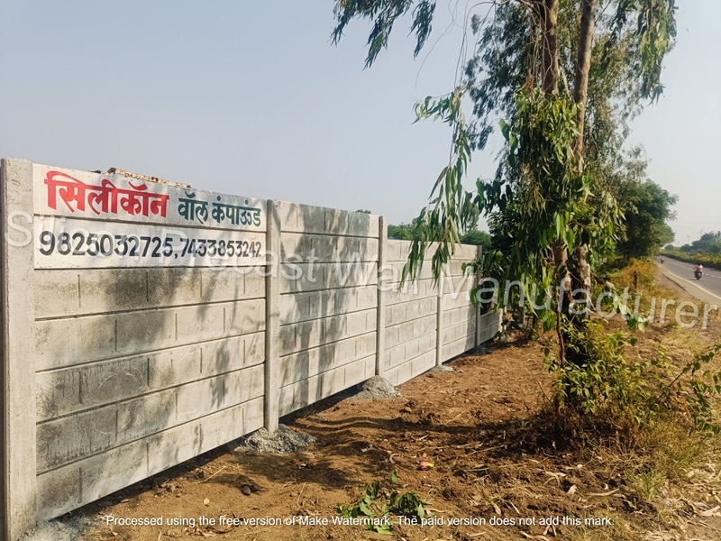 | RCC Precast Compound Wall 7ft RCC Precast Compound Wall Wall Height 7 ft Panel Thickness 50 mm Built Type Panel Build Usage/Application Construction Colored Grey Material RCC Wall Type Compound Wall Grade... |
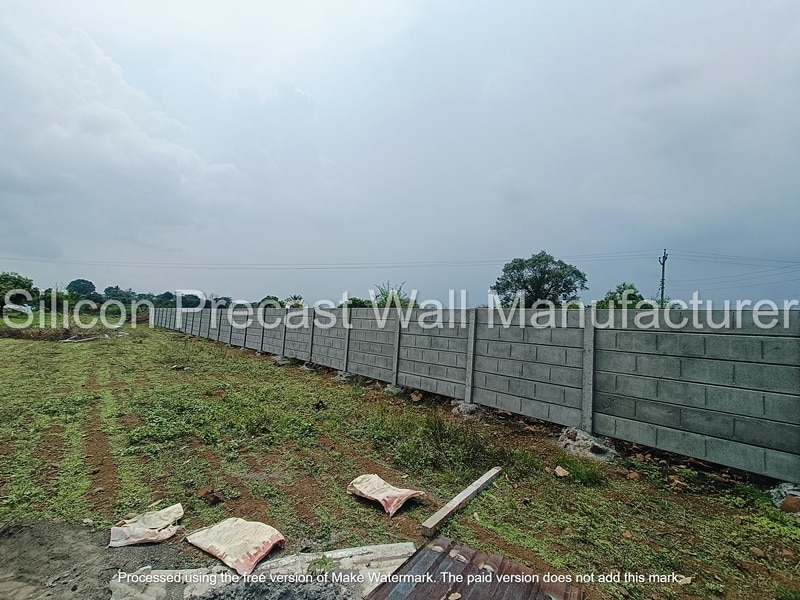 | RCC Precast Compound Wall 9ft RCC Precast Compound Wall Wall Height 9 ft Panel Thickness 75 mm Material RCC Grade Standard Technical Grade Wall Type Compound Wall Built Type Prefab Usage/Application... |
Frequently asked questions
What must contractors confirm before ordering an RCC precast compound wall in Nashik?
Confirm the surveyed boundary, approved layout, local development permission, road-widening or highway setbacks, drainage-reserve limits, and utility-clearance information before fabrication or excavation.
What controls are needed during a 7 ft RCC precast wall installation?
Set out the boundary from the approved drawing, construct the foundation and post pits correctly, and check post spacing, plumb, panel alignment, and joint fit during installation.
What extra checks apply to a 9 ft RCC precast wall installation?
A 9 ft wall requires additional stability checks because its height increases demands on the posts, foundation, alignment, and resistance to wind and site movement.
How should contractors complete RCC precast wall handover?
Match posts and panels to the approved component details, verify drainage and water flow, inspect alignment and joints, record defects, and hand over the completed work with the relevant installation records.
Related products
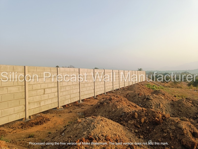 | Prefabricated Compound Wall Prefabricated Compound Wall Material Concrete Type Prestressed Height 6 Feet Usage/Application Security Thickness 50 mm Built Type Modular Build Color Grey Brand Silicon Precast... |
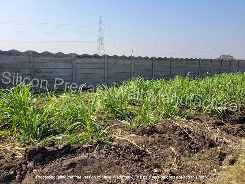 | Compound Wall Construction Services Compound Wall Construction Services Professional construction of compound walls for residential, commercial, and industrial properties Built using high-quality materials like bricks,... |
 | RCC Boundary Wall 7ft RCC Boundary Wall Thickness 50 mm Built Type Panel Build Size 7 feet Usage/Application Boundary Material RCC Brand Silicon Precast Color White Features: Constructed... |
Keywords